
The IoT Deployment Board 3.0

Introduction
The
new board: IoT Deployment Board 3.0, is ready to
setup the most projects in: IoT, domotics, robotics, control, lighting, Wi-Fi, web
server, MQTT, virtual instrumentation (dashboard), and a very vast variety of
projects. The limit is the imagination.
The
IoT Deployment Board 3.0 is based on the ESP8266-01 module, flashed with
MicroPython programming language. MicroPython is a compact (600 kB) package, a
very efficient implementation of the well-known Python 3. The installed version
is a fresh release of 2019.
With
MicroPython is very easy to program the board, and easy to find code examples
in almost everywhere, since Python programmers’ community is quite broad.
The
IoT Deployment Board 3.0 has a 1 MB flash memory from factory, with about ~400
kB free space for data and programs. Remember, Python is a very compact
language, so most of the programs are from few kB of size (1-10 kB).
Nevertheless, if a 4 MB flash memory version of the ESP8266-01 is desired it
can be provided upon request.
The
IoT Deployment Board 3.0 is an extension board of the ESP8266-01 that has been
provided with facilities to take advantages from inputs, outputs, and
communication ports, in such way that is much easier to work with different
types of sensors and devices that can be attached to their ports.
Next
is a summary with the specifications of the IoT Deployment Board 3.0.
Electrical Specifications
General Electrical Specifications
|
||||
Item
|
Min
|
Max
|
||
External
Power supply
(5 V
recommended)
|
4.5 V
|
12 V
|
||
External
Battery
( 4.8 -
6 V recommended)
|
4.5 V
|
9 V
|
||
Power
consumption
|
33 mW
|
1.3 W @ 5V
max: load
|
||
Internal
regulator
(800 mA
max)
|
3.3 V
|
3.36 V
|
||
Output
connector supply
|
0 A
|
1.25 A@ 5V
|
||
Operation
frequency
|
80 MHz
|
160 MHz
|
||
Output
collector current
|
0
|
40 mA,
each output
|
||
Item
|
Supported
|
|||
Aux VCC
output
Through
output connector and aux connector
|
YES
|
3 pins
|
||
Output
connector
|
YES
|
7 pins
|
||
Aux
connector
|
YES
|
4 pins
|
||
Power
led
|
YES
|
1 blue or red
|
||
GPIO
|
YES
|
GPIO-00
and 02
|
||
Led
indicator x 2
GPIO-00 and
02
|
YES
|
GPIO00-RED
GPIO02-RED
|
||
I2C and
OneWire protocol
|
YES
|
GPIO00 and
02
|
||
PWM
|
YES
|
GPIO00 and 02
|
||
Wi-Fi
hardware
|
YES
|
2.4 GHz
b/g/n
|
||
Flash
selector
|
YES
|
Pin header, jumper
|
||
Reset
Bottom
|
YES
|
SMD push
button
|
||
USB-to
serial UART connector
|
YES
|
Pin header
|
||
MicroPython
installed
|
Yes
|
Ver1.1
2019
|
||
Easy
connectors for input/output pins, led indicators, driven outputs as open
collector for higher loads, internal power regulator, and a wide range of power
supply are some of the features
that let the designer to be very comfortable in the designing, wiring the
hardware, and programming in any project.
Next
is the specifications of the Board connectors:
Connectors
Connectors
Specifications
|
||
External power supply
|
DC female jack, 5.5 x 2.1 mm Socket C26
|
|
External Battery
|
pin header 1x2 male 2.54 mm (1 row, 2 pins)
|
|
ESP8266 socket
|
2 x 8 vertical female 2.54 mm
|
|
Output connector
|
Pin header 1x7 vertical female 2.54 mm
|
|
Aux connector
|
Pin header 1x4 vertical male 2.54 mm
|
|
Flashing selector (jumper 2.54 mm)
|
Pin header 1x2 vertical male 2.54 mm (CN3)
|
|
Reset push button
|
SMD, SPST IP40, 3 mm (SW2)
|
|
USB-serial UART connector 1x3
|
Pin header 1x3 vertical male 2.54 mm (CN2)
|
|
Table 2. IoT Deployment Board: connectors
specifications
Physical Description

1-Power led
2-Main Output connector
(see figure 3)
3-IN/OUT GPIO LEDs
4-SW2/Reset button
5-CN3 Flash jumper (see
figure 3)
6-CN2/UART. Serial USB
cable. (see figure 3)
7-Aux connector
8-Battery In (see figure
3)
9- Power Supply connector
Connectors Description


The USB-serial cable could be any generic one. It should looks like this:

Board should look at this picture:

Now an
appropriate driver software must be installed in the computer.
Most
cases with Prolific driver, Windows system install a driver that does not work,
and this is done by default. User needs to install a new one and change the
driver version. Recommended Prolific driver version that proves to work is the 3.3.2.105
dated from 27/10/2008.
Prolific
driver 3.3.2.105 version can be found on Internet, anyway, is also
available from here:
Of course you can find a newer version of Prolific driver on Prolific's web site.
For Windows OS in:
And for MAC OS version:
Newer versions diffrent of the Prolific driver 3.3.2.105 have not been tested yet.
Once
the correct driver version 3.3.2.105 (in our case) is installed, proceed to change the driver
version, following the procedure as depicted in scheme below:
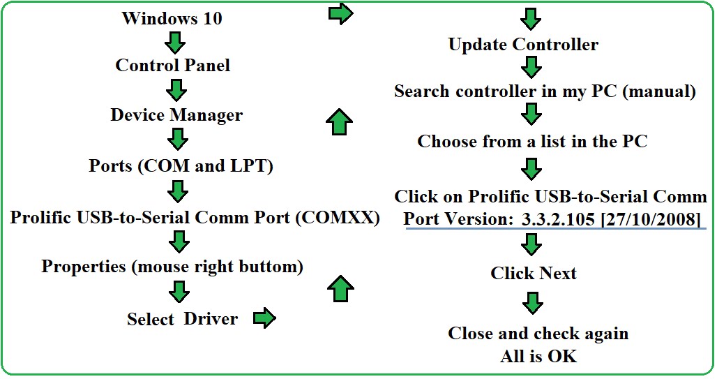
Follow the scheme, then select
the version 3.3.2.105 dated from 27/10/2008.
At the highlighted point you should see the following screen:

Then select the .3.2.105 dated from 27/10/2008.
The above mentioned procedure is only neccesary in the cases where the Operating System dooes not recognize the device, because driver compatibility.
Then proceed to check if everything is correct:
In
Windows, open the control panel, and then select Device Manager. Expand the
Ports (COM and LPT) tree. You should see Prolific driver USB-serial indicated.
Check
the COM where is installed, see figure below.
If
the COM where driver is installed has some conflict with other COM it can be changed
by selecting Port Configuration tab, then in advance options there is a
drop-down list, there are 256 COM ports, select any COM that is currently not
used.
Select
properties from right click menu, and click on controller tab, then check that the
information shown is consistent with driver version 3.3.2.105 already referred
here.
Figure
below is showing the controller information, indicating that the current driver
is the desired one.

To Flash Your Board
Your
IoT Deployment Board is already flashed with a fresh released of MicroPython.
But in any case, if user decide to burn or flash a new firmware user can do it.
To do, just power off the board and short with jumper CN3 connector. Then, power up your board. Use a program to flash
like Nodemcu Flasher, Arduino or your favorite program. You can download
Nodemcu Flasher from:
For
Win64:
For
Win 32:
Nodemcu
flasher program has a very intuitive interface.

Then
you have to download a firmware version for your board. Valid file must have *.bin
extension. Release version of MicroPython can be download from:
In
Firmware for ESP8266 boards section. Try to select the latest stable firmware.
At
the time of writing this book the earlier version is the:
Once
you have selected the flasher program and the firmware you can proceed to burn
as follow:
·
Click in the Config tab and select the path where
the firmware is located in your PC.
·
Click in the Advance and check: Flash size = 1
Mbyte, Flash speed = 26.37MHz, Baud rate = 115200, and SPI Mode = DOUT.
·
Click in Flash button.
If
everything goes well, flashing will start. A Green bar is advancing up to
complete the process, you will be prompt when process is finished. Then power off
the board, remove the CN3 jumper. Then power up the board again. Now the board
is flashed, but to test the program follow the section about to prepare the
software.
You
can also Deploy the firmware by using esptool.py program as described in the
tutorial available on:
Reset Button
Retest
button is also shown in connectors description. Any time you need to reset board (hard
reset) you can press and release this bottom. There also a way to reset (soft
reset) by pressing CTL+C, it will break the execution of any program.
Battery Operation
Board
can operate from battery power. Minimum recommended voltage is 4.8 V. Battery
can be from lithium, Ni-MH, Ni-Cd, or alkaline type. Capacity will depend on
the load; a 2000 mAh is a good capacity for battery. Please be careful to
connect the battery with the correct polarity, because there is not internal
reverse protection, so be sure to connect positive and negative to their respective
battery electrodes.
If
a voltage decreases below 4.3 V, the execution program can be stopped or
frozen.
Battery
will be in a charging state if it is connected while using power supply from
external source or charger. Once the external source is disconnected battery
will be immediately supplying .
Connect
the battery through Battery connector as shown in the connectors description. You will see +5V and
GND indicators on the board.

Communicating and programming the board
Once
you have the hardware ready you will need to prepare the software. For this,
you can use whatever serial communicator or terminal emulator software like PuTTY (Windows, Mac, Linux), Tera Term (Windows),
Arduino IDE series monitor (Windows, Mac, Linux), Sublime, esptool.py program, or your
preferred one. All mentioned here are free to use. Download your preferred.
In
this book we recommend and use uPyCraft IDE (Windows, Mac, Linux). uPyCraft IDE is a very
simple, intuitive and practical application that provides a good starting point
for developers.
(File is encrypted the password is: IoTDev)
Enough
information about how to use and an user manual of uPyCraft IDE is also available to download in link below:
You can find a big support for MicroPython at:
Please
download and install: uPyCraft IDE or your preferred Python editor on your PC.
In our case, we will use uPyCraft IDE as default MicroPython editor
Open
uPyCraft IDE and setup the connection parameters like indicated in the figure below.
Go to
Tools menu. Then, in serial option check that COM shown is the same where your
USB-serial driver was previously installed. In our case is COM5.

Then
go to Preferences in same Tools menu. Check about baud speed. Most of time it
is 115.200 bauds by default. See figure 13. But, if some reason you see some
illegible characters when communicating please try with lower speed, like 9600
or other different baud until you see all legible characters. Let the rest of
parameters as default.

Again, in same Tools menu, check is the ESP8266 board is selected.

Now
you can power up the IoT Deployment Board with USB-serial Cable plugged.
With
selected options in uPyCraft IDE proceed as follow: press connection link icon as
indicated in the figure 15. If all goes well, a Python prompt (>>>)
is shown in the REPL console section of the uPyCraft.

Note:
if you press again the icon link it will disconnect the board, then the prompt
will not be shown anymore. In this case, press again the icon link.
REPL
means Read-Eval-Print-Loop, is a high interactive language console, basically,
takes user input, and evaluates and returns the result. This method is
particularly adopted in scripts-based programming languages, like Python.
If you
see the command prompt, you can be sure the board is already connected.
Now push
the reset button on the board, and you will see a new message showing the installed
MicroPython version and some others information after the board has
successfully completed the boot up operation.
You
can interact to the Board by means of Console or by program. In console you can
write and execute immediately the code. But if you need to make a program or
function to be downloaded into the board you will need to write some lines of
code. Then use the program area.
To
run the program, you need to put a name and to save it in your PC before to
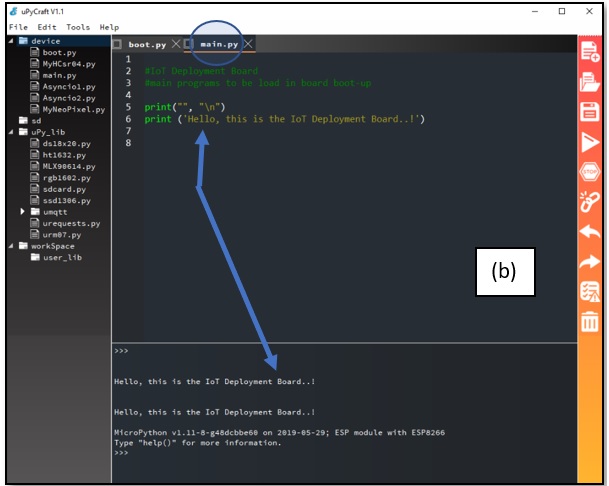
download and run in the board. Then click in download & run icon (see the above), program will be automatically downloaded and run in the board.
In the
uPyCraft you have a device, uPy_lib, and workspace folders. In the
device folder there are all programs current downloaded into the board. Two of
them are very important boot.py and main.py. The first one,
boot.py, has a boot up sequence of the board, and it is created by default. The
second one, main.py, can be created after and can be invoked or not by boot.py.
It is used here to load all programs you desire after the boot up sequence
(boot.py) is loaded.
You will
see an example of using main.py in following sections.

Now,
everything is okay….!
Download an Run Programs
You can program in the uPyCraft environment and then download and
run to your board.
Programs that are
downloaded to the board remains in the device folder. So if you want to execute
a particular one just double click in the device folder, then it will appear in
the program area, then press icon to Download and Run, it will be executed.
Also, you can
program in a different environment and then select the file from file menu in
uPyCraft and press Download and Run button, it will be executed.
You have so many
ways to program and run as it is completely flexible.
Additionally, you
can download a zip or rar file containing many functionally examples that works in the
board.
The compressed package
contains a list of the program that can be downloaded and try for any purpose
as free to try “as it is”.
So far,
the list contains the following programs. However, the list may change at any
time, as new programs will be added continuously.
- Blinking two leds.py
- Blinking led.py
- Data types.py
- Defining_my_function_examples.py
- Errors.py
- Hello_world_with_input.py
- http_server_1.py
- http_server_DHT22.py
- http_server_DS18B20.py
- http_server_DS18B20_Gauge.py
- MyHCsr04.py
- MyHC-SR501.py
- MyNeoPixel.py
- MyOLED.py
- MySensorDTH22_Test.py
- MyClass.py
- MyFunctionExample.py
- MyServo.py
- Testing_import_my_modules.py
- Toggle.py
- System_data.py
- Timer_0.py
- Timer_1.py
- Asyncio1.py
- Asycio2.py


